Define Setup and Work Offset
IN THIS ARTICLE
All the machining operations are grouped to under a SETUP parent item .
To add a new setup :
- On a empty project, you can click on one of the available button in side screen.
- From menu -> Lathe or Mill and pick on of the "New Setup: ... " item.
You can have setup for :
- Vertical Mill
- Lathe
- Lathe with Live Tool (C Axis)
From start screen

From Menu

Setup Screen Overview
Click on setup item in treeview to open setup screen definition .
In setup screen you can define properties like setup name, origin (G54, G55 , ..), define origin point , G-Code program number , select machine definition , set disengagement absolute coordinate.
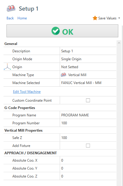
You have a different properties depending on selected machine type .
Lathe Related Properties
When "LATHE" or "LATHE with C Axis" machine type is selected, you have the properties below.
Spindle Rev. Limit : It's the maximum spindle revolution limiter. This value it's used from post processor in operation header template.
Approach Mode - Interpolated : In approach and disengagement movements , the tool will move interpolating both X and Z axis.
Approach Mode - Tailstock : To avoid tailstock body, the approach will be done moving first the Z axis and then the X Axis. The disengagement move will be done moving first the X axis and the the Z axis.
From the 2nd setup you have also :
Flip Stock : The stock model is flipped in the setup.
Stock Translate Z : It move the stock in z axis. If you use the flip stock, use a negative value to move the stock in Z+ direction.
Additional Setup

If you add a second setup , you have to choose if you want to continue from previous setup, or create a new setup.
If you choose NEW SETUP , a different file will be created for G-CODE.
Otherwise if you select CONTINUE FROM PREVIOUS SETUP , the code will be added in the same file .
Is also possible change position of the stock, trough action STOCK POSITION.
If you are doing a lathe part, probably you need only to flip the 3D model of stock. In this case check the FLIP STOCK property.
Stop Program Message : It's the user message printed in gcode between this 2 setup.
Define Work Offset
Use the ORIGIN property to define the WORK OFFSET for every operation linked to setup.
The default value is "Not Setted", so you in nc program the work offset is not defined.
You can also choose a value from WCS 1 to WCS 6. Any WCS will have as output a different GCODE . By default this code may varies from G54 to G59.
Is possible edit these values from post processor dialog, Input "origin" in filter box and edit output codes accordingly to your needs.

Below an example g-code , you can see the work offset gcode in second line.
N5
G54  <<- THIS CODE DEFINE THE WORK OFFSET TO USE
(FACE TURNING - ROUGHING)
M9
G99G18
G50S500
...
The work offset is necessary to define a specific position in machine work space as the coordinate origin X0 Y0 Z0 .
The effective machine position of every work offset is defined in a table in machine controller.
Multiple Work Offset with Vertical Mill Setup
With vertical mill machines you may multiple vise and you want to repeat the same program on every vise.
Every vise will have a spefic work offset ( G54 , G55 , G56 ... )
From setup screen, set ORIGIN MODE as Multi Origins , then enable all the origin you need . In the example below you can see enabled WCS 1 , 2 and 3.

Take a look at gcode below, the same operation toolpath is repeated 3 time.
Every time with a different ORIGIN code ( G54 , G55 and G56 )
N1
G54
(FACE MILLING - ROUGHING)
(T16 R345 PP D 50MM)
T16 M06
G94 S1592 M03
G00 G90 X16.667 Y80.
G43 H16 Z100. M08
Z50.
G01 Z0. F5000.
/// skipped code ///
G00 Z50.
Z100.

G55
(FACE MILLING - ROUGHING)
G00 X16.667 Y80.
Z100.
Z50.
G01 Z0. F5000.
Y75. F425.
/// skipped code ///
Z100.

G56
(FACE MILLING - ROUGHING)
G00 X16.667 Y80.
Z100.
Z50.
G01 Z0. F5000.
// skipped code ///<br>
Post Processor : Be sure you have the {ORIGIN} tag in 'Operation Head Code' and 'Operation Head Code (without toolchange)' templates.
Approach / Disengagement Absolute Coordinates

And this is the output g-code-
